Pages

Showing posts with label 3D Via. Show all posts

Thursday, November 3, 2011

Free 3D CAD Viewer downloadable software compariso


A useful tool in today's world of engineering is to have software which can view 3D CAD models but without having all of the tools of a CAD software system thus making the viewer extremely cheap (ideally it would be free). Here is a table comparing a few different CAD Viewer software programs and in the coming weeks I will be offering a more descriptive breakdown of each one including their strengths and weaknesses. 

Monday, January 10, 2011

S&S Spaceshot CAD Model Recreation


I started a 3d computer model recreation of a 3x3 size Spaceshot launched thrill ride attraction engineered by S&S Worldwide. I embedded a video of Power Tower at Cedar Point below (note the seating configuration is slightly different).

Tuesday, August 10, 2010

New 3D XML Model Uploaded to 3D Via

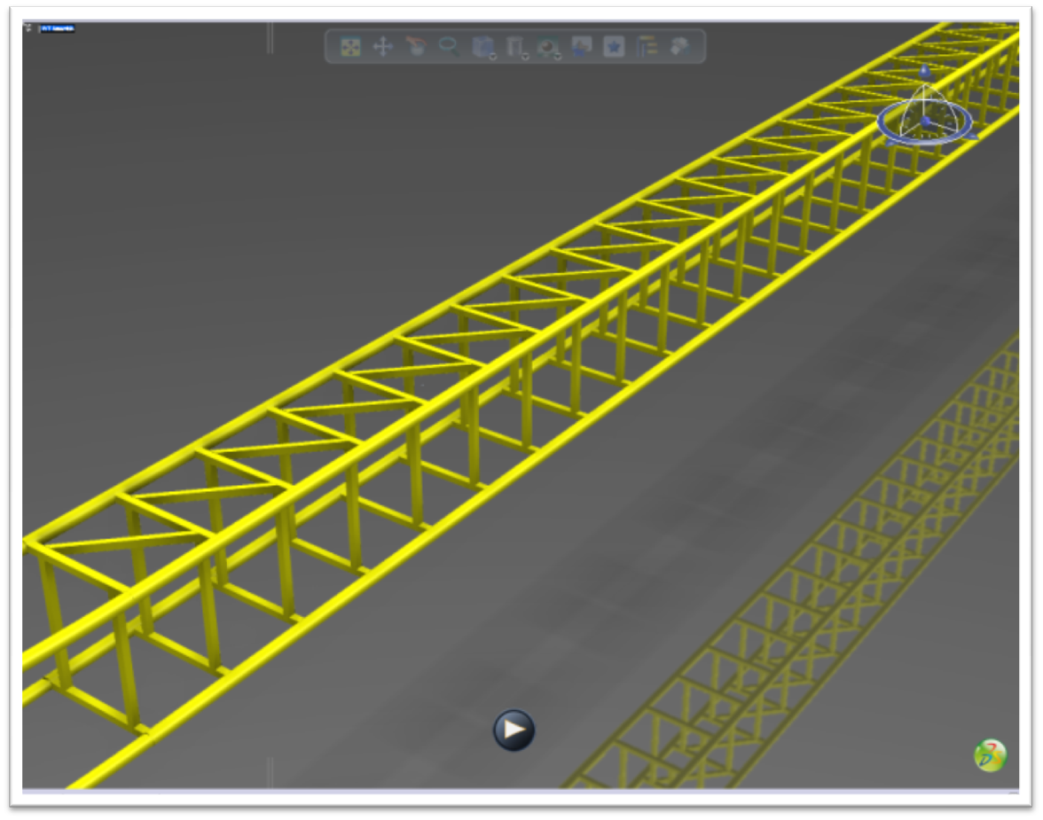
Today, I uploaded a new CAD model to 3D Via in 3D XML format. This is the current state of my next generation version of the cantilevered roller coaster. The main difference has been the change from a cantilevered I beam to a beefier truss configuration.

Monday, March 8, 2010

Update on CATIA Train Model

I promise to do a complete "How to" later on, seeing as how this is the CAD Systems Help blog and I don't think I've done much to help other than show off my own work. Here is my progress after about 8 hours of work on the Locomotive 020T Decauville CATIA model, which I uploaded to my 3D Via page. What do you think?

Wednesday, March 3, 2010

AutoCAD to CATIA: Train CAD Model

I'm working on a new project where I am taking AutoCAD drawings of a steam locomotive and recreating it in 3D with CATIA. After about 4 hours of work here is the result (from 3D Via):


I will be writing a full how-to on this later so stay tuned!

Tuesday, February 23, 2010

The Future of Assembly Instructions: 3D


You buy a bookcase from your local cabinet store. You want to repair a component in your car engine. For the first task, you may be supplied with paper instructions that are very confusing and inconvenient. There are five copies in five different languages when all you want is English. Or, for task two, there are no instructions but you’re not a mechanic so you have no idea what to do.  In the future, both of these situations will be remedied by 3D Instruction and How-to manuals. Gone are the days of paper instructions. Welcome to the era of looking on your smart phone for a step-by-step simulation of how to repair your vehicle without any prior mechanic’s knowledge. 3D Via, xml, and PDFs will be supplied on a disk or flash drive or, even better, as an internet downloaded included with the cost of the product. This is the future. Check out the video and article link below.

Friday, February 5, 2010

I Made the 3D Via Top Ten Models of the Week List


The best models uploaded to 3DVIA.com during the week of Saturday, November 1st through Friday, November 7th are highlighted here. Your band now has both a scary guitar, a snare drum and a really cool set of towers to play in, but will the Abstract Propeller and the Flummox Roller Coaster keep the repo men distracted long enough for you to move the Camaro and Sunbeam somewhere safe. You better hope that the Army truck is finished being lined-up on the jig so you've got some back up on the way…otherwise you may end up making friends with the smiley guy in the hearse.

Check it out!

(Mine is the Flummox roller coaster in case you did not know).

Saturday, January 23, 2010

The Future in 3D

If you’ve been following CAD Systems Help you may have seen some of the amusement park ride 3D computer models we have been working on in our spare time (I promise this blog will have more CAD examples than just roller coasters). In those earlier posts, all we presented you with were 2D pictures of the rides. You could only view the model from the view that we gave you. What if you wanted to view the model from a different angle? Well now you can.  We have converted all of our original Catia models to 3D XML format and uploaded them to 3D VIA. Several of our works-in-progress are embedded below for your enjoyment. Feel free to explore the actual 3D models yourself!

For those who are not familiar, 3D XML is a universal, lightweight XML-based format that enables users to share live, accurate 3D data quickly and easily. A free player is provided by Dassault Systemes (you will need to install a plugin in order to view our creations). The models come with no history, meaning you can’t see exactly how they were built, just what the end result is.

One of the coolest features of 3D VIA is the ability to integrate high quality 3D models within Word and PowerPoint documents, which is as easy as dragging and dropping the 3D XML file into the Office document. This also enables users to view interactive, real-time 3D applications in a Web browser or stream them from a website.

What does this mean for the amusement park industry? These tools can be a great resource for ride design and would enable more efficient communication between the manufacturer and the amusement park. Gone are the days of carrying around huge sheets of plain, two-dimensional drawings that take money to print and time to revise. It’s much easier to visualize a new attraction if you can see a model in 3D and even better if the park can zoom in on specific features and view it from any angle. This software enables the park to give instant feedback on what they do or don’t like about their upcoming ride. The biggest advantage of 3D VIA is that it enables all of this to be achieved without the park having to own expensive CAD software.
In fact, another great feature is the complete three-dimensional models can even be viewed on your iPhone! 3D Via’s new mobile app allows you to position and overlay 3DVIA models on your iPhone photos and e-mail or share with friends. Check out an example video:


evisions can be made and viewed in real time, again increasing efficiency and communication. This could help the park and manufacturer save money by decreasing design time. Attractions can be realized quicker and would need less lead time. The parks could save additional money because they wouldn’t need to hire a separate company to build a model of the ride for marketing purposes as they would already have exactly what they needed. It’s a win-win-win situation for operators, designers, and customers.


Intamin Ball Coaster
Vekoma Flying Dutchman
Water slide
Water slide
Wood coaster
Wood coaster
Steel coaster
Steel coaster

Click on the pictures above to go to the live 3D models. This is just a sample of how would work in real world situation (if it isn’t already being done).

Check out our project showcase site.
View some of our other non-amusement park related models.

For more amusement park news and features visit Coaster101.

CATIA Model: S&S Screamin Swing

Today I decided to attempt to model an S&S Screamin Swing thrill ride in CATIA V5 R19. Here are two pictures and the 3D xml of what I made today. It's a little rough around the edges but you get the idea. I made up all of the dimensions since I have no idea what they actually are. I think the scale actually came out quite well. Not as exciting as a roller coaster but the file size is much smaller! You can see some of my other creations at Campus3ds website. Enjoy.


Friday, January 15, 2010

Wicked Twister Roller Coaster CAD Model Tutorial

If you are a frequent visitor to Coaster101, you may have seen some of my CATIA amusement park ride computer models, like this. You may also have been asking yourself or wondering how I created those computer models. Well today I am going to explain in a little bit further detail on the process I have used to recreate those attractions on the computer.


 I use a program called CATIA (Computer Aided Three-dimensional Interactive Application), which is the most powerful and widely used CAD (computer aided design) software of its kind in the world.


 If you’ve ever used No Limits simulator there is an excellent Wicked Twister recreation so I am going to use that to help me out. Keep in mind that this is just one approach of literally thousands of different ways of doing it. If you have a other suggestions I would love to hear them!
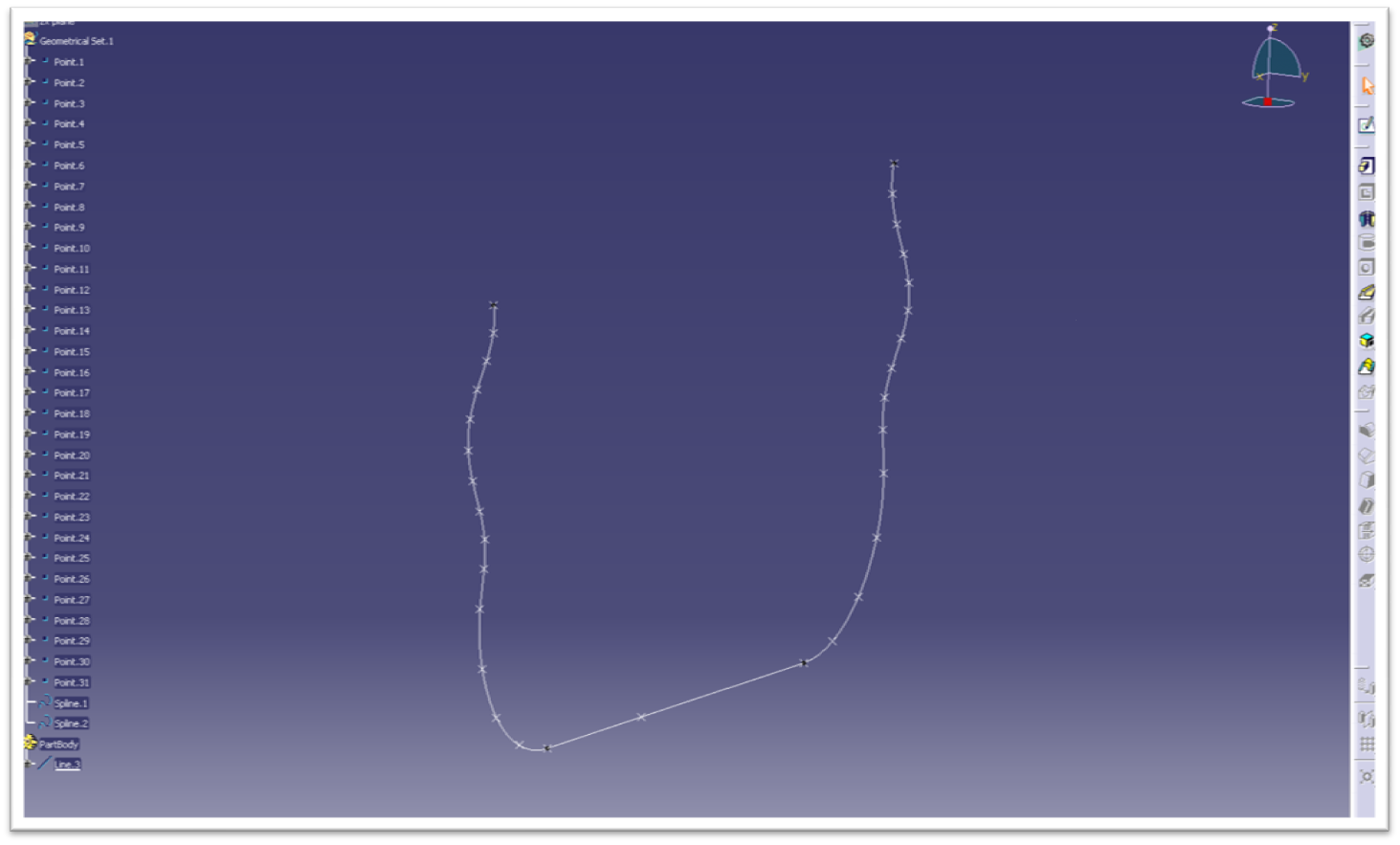
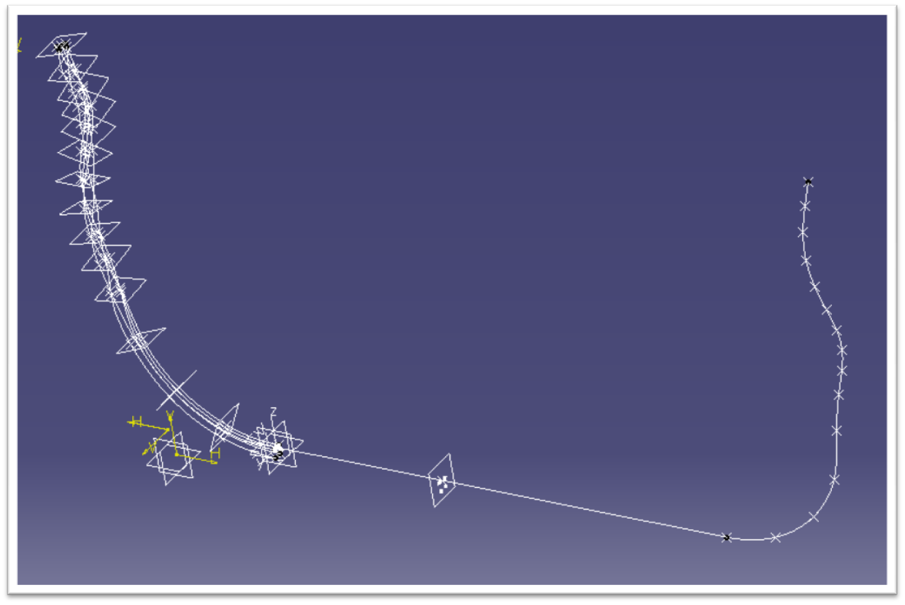
The first thing I did was get the coordinates from all of the node points in the No Limits model. I created all of these points in a CATIA part. Be careful of the axis system, CATIA’s default axis is not necessarily the same as No Limits in terms of which direction is X, Y, or Z is. Next, connect all of the points with the spline command. This is the result thus far. You can see the basic profile layout, also called the center or heartline of the coaster.
wt1
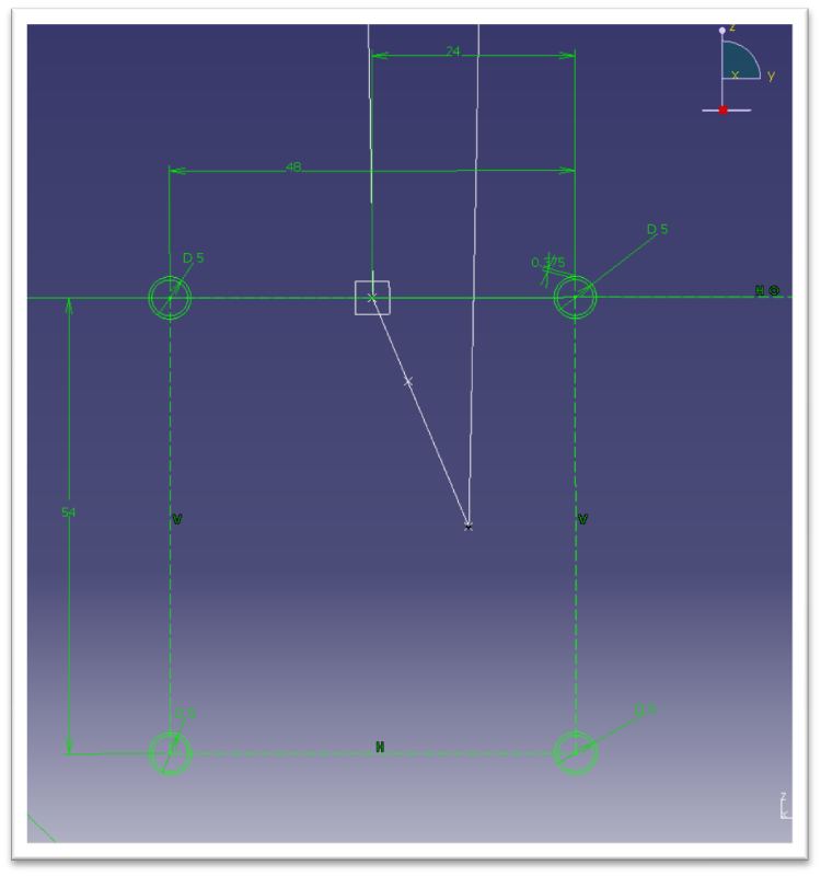
Now we need to make the shape of the track. This are the dimensions I used for the track.

wt2

I have never seen an actual spec from Intamin so I had to do a little investigating and guess work. This is what’ve I’ve come up with. From an old Millennium Force flyer I learned the rails are 5 inches in diameter and only 3/8 inch thick (even at the highest g-force areas). Someone gave me an educated guess that the rails are 48 and 54 inches apart at the centerlines so I went with it. The rectangular tubes that hold the rails together I assumed to be 3 inch square tubing.

The important thing to notice now is that the rails are zero degrees with respect to the horizontal axis. This becomes critical when we get to the two towers and this angle will gradually increase, which makes the twisting helix.
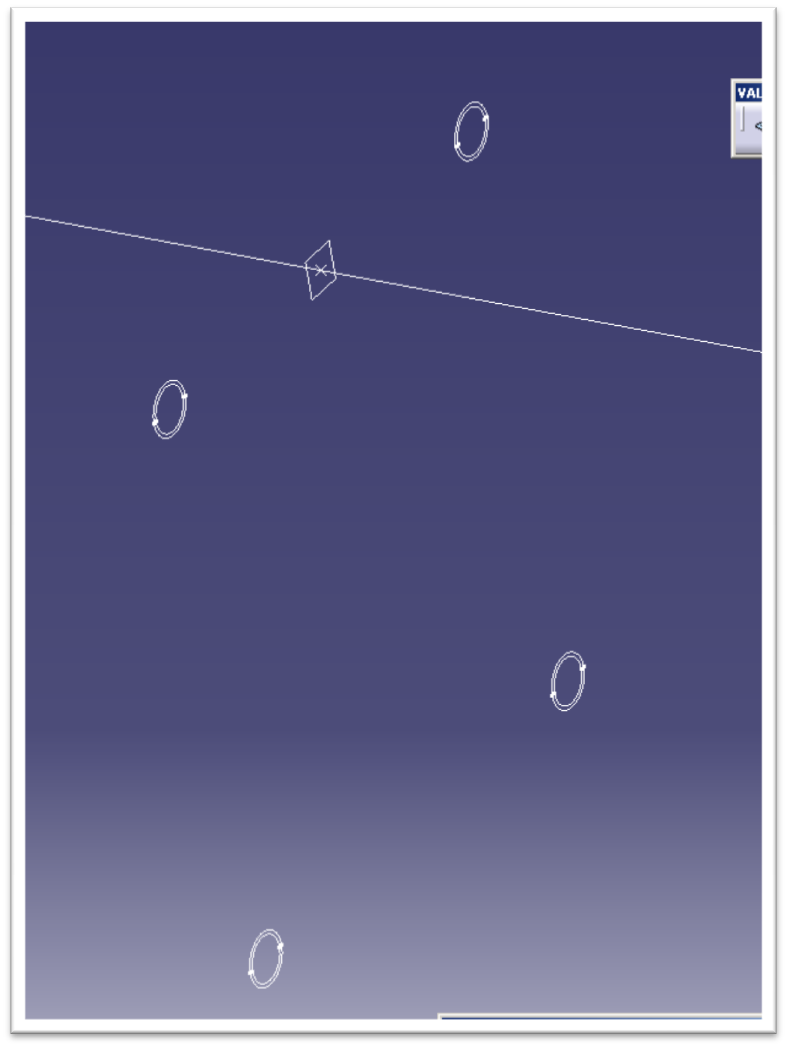
The basis of everything is right here. The centerline and the sketch for the rails.
wt3
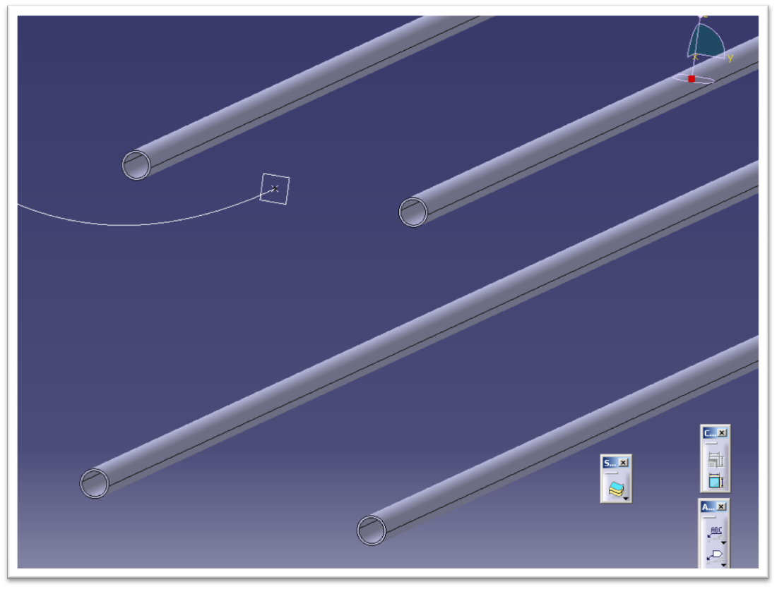
After I created the sketch for the rails, I used the rib command to extrude their shape throughout the length of the station and launch track segments.
wt4
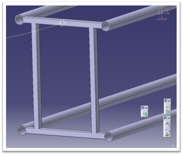
After the rails were created I had to construct the connecting tubes, pictured here.
wt5
I used this image for reference as well.
wt6
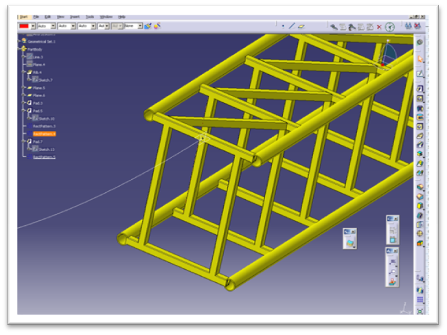
Next I began adding the diagonal cross bars. I only have to sketch one of them on the straightaway then I can simply pattern the rest.
wt7
wt8
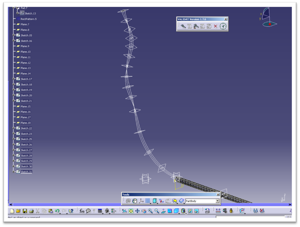
The hard part now is the spikes on the end. Remember the critical angle I mentioned earlier? At every node point starting from the fourth one out of the station the track now rotates 45 degrees about the center. I created points where the rails will go and then connected them with a spline, giving the shape you see here. I can then sketch a circle on the end and rib it through the spline, just like I did earlier, thus creating the rails.
wt9
This is what all of the construction geometry looks like, and by construction geometry I mean all of the points, planes, lines, splines, axis and sketches. These elements are used to construct the solid.
wt10
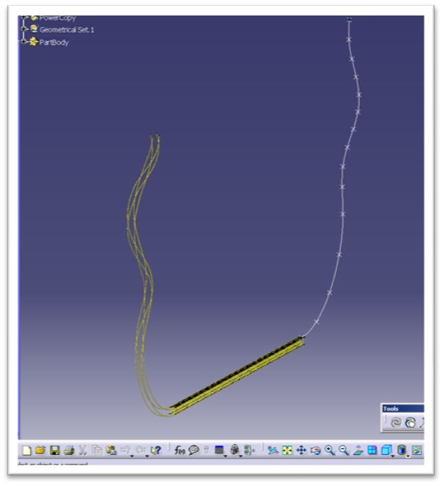
Next, I ribbed the twisting splines. After all of that, here is the result of our progress, which is as far as I am going to go today. The only other thing I will do now is to quickly construct some simple concrete footers and steel supports for reference.
wt11
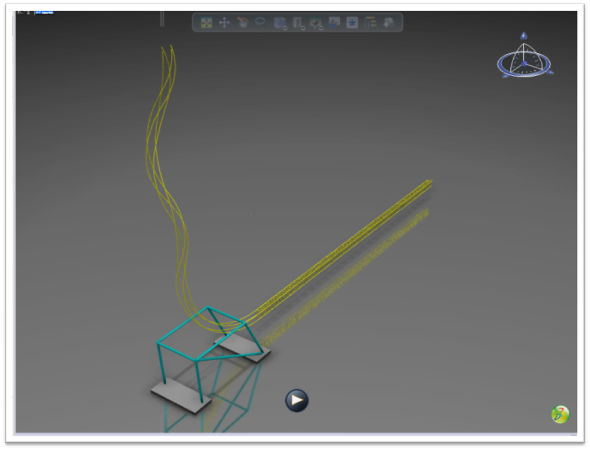
I saved my assembly as a 3d xml file and exported it to 3D Via and here it is for your enjoyment.
wt12
wt13
Would you be interesting in learning more and reading additional features like this one? Let us know in the comments!

Thanks for reading.

43BGT8V3B6TP