Pages

Showing posts with label Coasters. Show all posts

Sunday, April 7, 2013

3D Boat Design Software

3d boat design software
I recently found a nice 3D boat design software to help you design anything that floats. If you have ever wanted to design a boat yourself then this is the program for you. 3DBoatDesign is a versatile CAD software package that is easy to use yet also powerful at the same time. Some feature of 3DBoatDesign include enhanced hydrostatic calculations, easy 3d scaling, rotating, and moving, hull sculptor, resistance calculations and more!

3DBoatDesign is to boats as NoLimits Simulator is to roller coasters - simply the best available software to everyday consumers and affordable too!
cad boat design

Download 3D Boat Design today and starting designing the watercraft of your dreams!

Monday, March 19, 2012

How do you simulate rolling in CATIA?


This is anupdate of an older post. I've created a brand new tutorial with step-by-step instructions detailing how to use CATIA V5's DMU kinematics workbench to simulate a rolling object.

First, in assembly design, create a new product and insert two new parts, one name Wheel and the other Ramp. 


I've explained this before but as a real quick overview, to create my ramp I used three sketches (overhead, side profile, and rotation about itself sketch) and combined them with laws. The wheel is a simple sketch and pad command. On my ramp I have two parallel curves 5mm apart. On my wheel I also have two parallel curves offset from each other 5mm. I added a point to one of the edges of the wheels so you can see it spin around in a circle when we simulate it. 


Add a Fix constraint to the ramp to ensure it does not move. It's absolutely vital that the curves on the wheel and the curves on the ramp are tangent to each other. Even a 0.001 gap and it will not work. Use coincidence restraints to pair them together if you have to. Also make sure your ramp is nice and smooth and much bigger than your wheel.

Now it's time to go into the DMU Kinematics workbench. Create a new mechanism and set the ramp as the fixed part. I can constrain all degrees of freedom using only two joints. The first joint is a roll curve joint between curve 1 on the wheel and curve 1 on the ramp. This is a length driven joint meaning you will input the rolling distance over time from the start point. The second joint is a slide curve joint between curve 2 on the wheel and curve 2 on the ramp.


Once you get the hang of it you can simulate more complex systems, like a full-scale roller coaster! 

CATIA KINEMATICS ROLLING TUTORIAL VIDEO: 


View my Introduction to CATIACATScript Macros Video Tutorial.

Tuesday, July 19, 2011

How to simulate rolling kinematics tutorial

How do you simulate wheels rolling down a hill or track in CATIA? A reader recently asked if I could put together a tutorial for the kinematics rolling simulation that I created. This may not be extremely detailed but should give you a pretty good idea of the steps to take when trying to simulate rolling in CATIA. This was one of the preliminary tests I ran before attempting to simulate my entire roller coaster model. Download the kinematics rolling powerpoint tutorial here.


How to simulate rolling in CATIA DMU kinematics workbench tutorial.ppt download

Monday, June 13, 2011

Robocoaster Model


I constructed a recreation of a Kuka robocoaster in CATIA. I used the car from my cantilevered roller coaster simulations to save time. The track is created using three sketches with laws (one overhead, one side profile, and one for banking). I made this in about a day so please excuse the lack of detail. The purpose was more to show proof of concept that this was possible to create with CATIA.


For the simulation, I used the DMU Kinematics workbench. There are four user input commands to (1) drive the robotic arm down the track (2) horizontal rotation about the z axis (3)vertical rotation of the upper arm (4) rotation of the seats about the upper arm axis. In fact, in one of the video clips there is a fifth command- the rotation of one of the domes on which video would be projected, similar to the Harry Potter ride at Universal Orlando.


Monday, January 10, 2011

S&S Spaceshot CAD Model Recreation


I started a 3d computer model recreation of a 3x3 size Spaceshot launched thrill ride attraction engineered by S&S Worldwide. I embedded a video of Power Tower at Cedar Point below (note the seating configuration is slightly different).

Saturday, December 11, 2010

Coaster Model Update

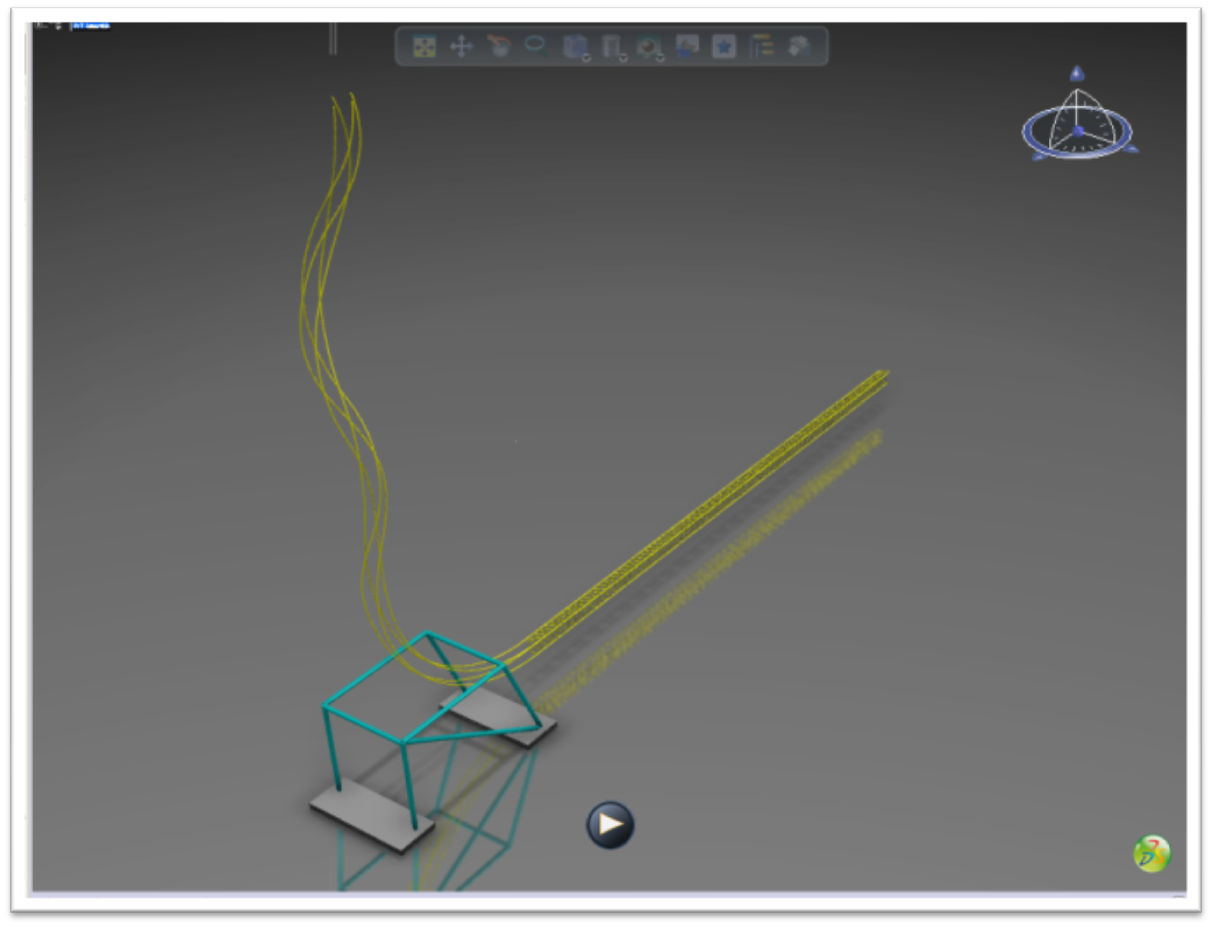
Quick update on the cantilevered roller coaster model. I used my VB catscript to quickly and easily create the cross-ties for the upper and lower rails. I also modeled all of the supports and cement footers. Pictured is one of the "side/head knocker" effects where it looks like you are about to run into a post before the cantilevered car serves out of the way in the nick of time. There is also an overview of the layout. Video coming soon!


Monday, November 15, 2010

Automatically Create Cross-ties for a Roller Coaster Using VBA CATScript

Are you looking for a way to pattern an object multiple times in CATIA? How do you write catscripts in CATIA? Are you looking for a CAD model roller coaster? You've come to the write place.

If you been following this blog then you're probably aware of my work on the cantilevered roller coaster concept model. I recently created a new track to simulate the motion capability of the vehicle. I needed a quick and easy way to create all of the cross-ties which hold the two running rails together in order to create a CAD model which is as realistic as possible. At first, I was using patterns for each section of track: rectangular pattern for straight sections and circular patterns for turns and hills. This was a very time consuming process. My model contains two track that are currently around a thousand feet long. With a little bit of help from a CATIA forum, I was able to put together a CATScript which quickly and easily creates all of the cross-ties at once.


In order to get this work there are a few things that needed to be done. The rails had to be in their own separate part file. There had to be a geometrical set named "Rollercoaster." You have to select the guide curves for each rail before running the VBA code.

Here is the procedure used in the CATScript:

1. Place point1 on guidecurve1 and point2 on guidecurve2 each at equal distance from their start points.
2. Create plane normal to guidecurve1 through point1.
3. Find an intersection between normal plane and guidecurve2
4. Use near operation to select element from intersection that lie on guidecurve2 (in case if there are multiple intersections). Use point2 as reference element. Then redefine point2 to point found.
5. Place a tangent line to guidecurve1 at point1 using AddNewLineTangency method with length limits -1.5'' and 1.5'' (tangentline1)
6. Place a tangent line to guidecurve2 at point2 using AddNewLineTangency method with length limits -1.5'' and 1.5'' (tangentline2)
7. Look for points at ends of tangentline1 with AddNewPointOnCurveFromPercent method using 0% and 100% values.
8. Look for points at ends of tangentline2 with AddNewPointOnCurveFromPercent method using 0% and 100% values.
9. Connect points from 3 and 4 with lines using AddNewLinePtPt method.
10. Create new fill object using AddNewFill method and add tangent lines and lines from 5 to it using it's AddBound method.
11. Create a pad using AddNewPad method of ShapeFactory object of root part of active document.


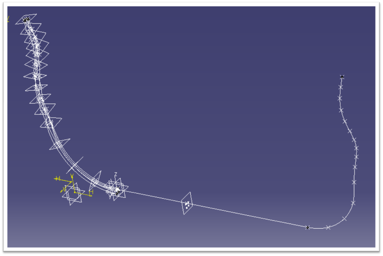
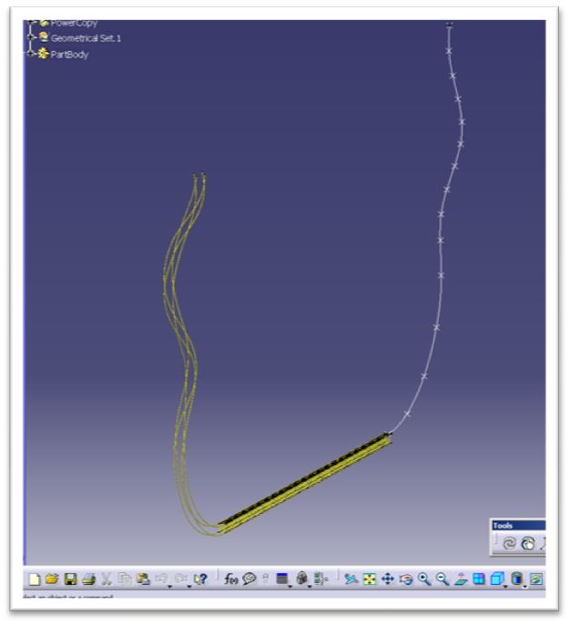
Pictured is the track before and after the macro is ran. Here is the complete code:

Automatically Create Cross-ties for a Roller Coaster
Option Explicit

Private Const ONE_FOOT_MM = 30  ' define number of millimiteres in one foot

Private Const STEP_LENGTH = 48  ' length between cross-ties, in feet
Private Const PAD_SIDE = 3      ' length of single cross-tie side, in feet


Sub CATMain()

    ' accessing part object
    Dim RootPart As Part
    Set RootPart = CATIA.ActiveDocument.Part
   
    ' retrieving target geometrical set named "Rollercoaster"
    Dim TargetGeoSet As HybridBody
    Set TargetGeoSet = RootPart.HybridBodies.Item("Rollercoaster")
   
    ' define partbody as work object
    Dim PartBody As Body
    Set PartBody = RootPart.MainBody
   
    RootPart.InWorkObject = PartBody

    ' accessing selection object for current document
    Dim objSelection As Selection
    Set objSelection = CATIA.ActiveDocument.Selection
   
    ' retrieving reference for first curve
    Dim GuideCurve1 As AnyObject
    Set GuideCurve1 = objSelection.Item2(1).Value

    Dim refCurve1 As Reference
    If (TypeName(GuideCurve1) = "CATIAReference") Or (TypeName(GuideCurve1) = "MonoDimFeatEdge") Then
        Set refCurve1 = GuideCurve1
    Else
        Set refCurve1 = RootPart.CreateReferenceFromObject(GuideCurve1)
    End If
   
    ' retrieving reference for second curve
    Dim GuideCurve2 As Object
    Set GuideCurve2 = objSelection.Item2(2).Value

    Dim refCurve2 As Reference
    If (TypeName(GuideCurve2) = "CATIAReference") Or (TypeName(GuideCurve2) = "MonoDimFeatEdge") Then
        Set refCurve2 = GuideCurve2
    Else
        Set refCurve2 = RootPart.CreateReferenceFromObject(GuideCurve2)
    End If
   
    ' Retrieving guides' lengths
    Dim PartProd As Product
    Set PartProd = CATIA.ActiveDocument.Product
   
    Dim SPAWbench As SPAWorkbench
    Set SPAWbench = CATIA.ActiveDocument.GetWorkbench("SPAWorkbench")
   
    Dim objMeasurable As Measurable
    Set objMeasurable = SPAWbench.GetMeasurable(refCurve1)
   
    Dim GuideLength1 As Double
    GuideLength1 = SPAWbench.GetMeasurable(refCurve1).Length
   
    Dim GuideLength2 As Double
    GuideLength2 = SPAWbench.GetMeasurable(refCurve2).Length
   
    ' Equidistance points
    Dim PointOnCurve1 As HybridShapePointOnCurve
    Dim PointOnCurve2 As HybridShapePointOnCurve
    Dim refPOC1 As Reference
    Dim refPOC2 As Reference
   
    ' Normal plane
    Dim NormalPlane As HybridShapePlaneNormal
    Dim refNPlane As Reference
   
    Dim objIntersection As HybridShapeIntersection
    Dim refIntersection As Reference
   
    Dim objNear As HybridShapeNear
    Dim refNear As Reference
   
    ' Tangent lines
    Dim TangentLine1 As HybridShapeLineTangency
    Dim TangentLine2 As HybridShapeLineTangency
    Dim refTLine1 As Reference
    Dim refTLine2 As Reference
   
    ' endpoints for tangetnt lines
    Dim TLine1EndPoint1 As HybridShapePointOnCurve
    Dim TLine1EndPoint2 As HybridShapePointOnCurve
    Dim TLine2EndPoint1 As HybridShapePointOnCurve
    Dim TLine2EndPoint2 As HybridShapePointOnCurve
    Dim refTL1EPoint1 As Reference
    Dim refTL1EPoint2 As Reference
    Dim refTL2EPoint1 As Reference
    Dim refTL2EPoint2 As Reference
   
   
    ' lines, that connect endpoints of tangent lines
    Dim BoundLine1 As HybridShapeLinePtPt
    Dim BoundLine2 As HybridShapeLinePtPt
    Dim refBLine1 As Reference
    Dim refBLine2 As Reference
   
    ' fill object
    Dim objFill As HybridShapeFill
    Dim refFill As Reference
   
    ' direction line
    Dim DirectionLine As Line
    Dim refDLine As Reference
   
    ' pad object
    Dim objPad As Pad
    Dim refPad As Pad


    ' construction parameters
    Dim StepLength As Double
    StepLength = STEP_LENGTH * ONE_FOOT_MM
   
    Dim PadSideLength As Double
    PadSideLength = PAD_SIDE * ONE_FOOT_MM
   
    Dim curDistance As Double
    curDistance = StepLength
   
    ' accessing factory for creating shape objects
    Dim objHSF As HybridShapeFactory
    Set objHSF = RootPart.HybridShapeFactory
   
    ' accessing factory for creating solid objects
    Dim objHF As ShapeFactory
    Set objHF = RootPart.ShapeFactory

    ' define correct direction for second curve
    Dim SecondCurveDirection As Boolean
   
    Dim NormalDirectionDistance As Double
    Dim InvertDirectionDistance As Double
   
   
    ' get distance for normal direction
    Set PointOnCurve1 = objHSF.AddNewPointOnCurveFromDistance(refCurve1, 0, True)
    Set PointOnCurve2 = objHSF.AddNewPointOnCurveFromDistance(refCurve2, 0, True)
    Set refPOC1 = RootPart.CreateReferenceFromObject(PointOnCurve1)
    Set refPOC2 = RootPart.CreateReferenceFromObject(PointOnCurve2)
   
    TargetGeoSet.AppendHybridShape PointOnCurve1
    TargetGeoSet.AppendHybridShape PointOnCurve2
   
    RootPart.Update
       
    Set objMeasurable = SPAWbench.GetMeasurable(refPOC1)
    NormalDirectionDistance = objMeasurable.GetMinimumDistance(refPOC2)
   
    objSelection.Clear
    objSelection.Add PointOnCurve2
    objSelection.Delete
   
    ' get distance for invert direction
    Set PointOnCurve2 = objHSF.AddNewPointOnCurveFromDistance(refCurve2, 0, False)
    Set refPOC2 = RootPart.CreateReferenceFromObject(PointOnCurve2)
   
    TargetGeoSet.AppendHybridShape PointOnCurve2
   
    RootPart.Update
       
    InvertDirectionDistance = objMeasurable.GetMinimumDistance(refPOC2)
   
    If (NormalDirectionDistance < InvertDirectionDistance) Then
        SecondCurveDirection = True
    Else
        SecondCurveDirection = False
    End If
   
    objSelection.Clear
    objSelection.Add PointOnCurve1
    objSelection.Add PointOnCurve2
    objSelection.Delete
       
    ' start constructing pads
    Do While (curDistance < GuideLength1)
   
        ' place point on first curve at specified distance
        Set PointOnCurve1 = objHSF.AddNewPointOnCurveFromDistance(refCurve1, curDistance, True)
        Set refPOC1 = RootPart.CreateReferenceFromObject(PointOnCurve1)
       
        ' create plane normal to first curve at initially created point
        Set NormalPlane = objHSF.AddNewPlaneNormal(refCurve1, refPOC1)
        Set refNPlane = RootPart.CreateReferenceFromObject(NormalPlane)
       
        ' define second point as intersection of normal plane and second curve
        Set objIntersection = objHSF.AddNewIntersection(refNPlane, refCurve2)
        Set refIntersection = RootPart.CreateReferenceFromObject(objIntersection)
       
        Set PointOnCurve2 = objHSF.AddNewPointOnCurveFromDistance(refCurve2, curDistance, SecondCurveDirection)
        Set refPOC2 = RootPart.CreateReferenceFromObject(PointOnCurve2)
       
        Set objNear = objHSF.AddNewNear(refIntersection, refPOC2)
        Set refNear = RootPart.CreateReferenceFromObject(objNear)
       
        Set refPOC2 = refNear
        'Set refPOC2 = RootPart.CreateReferenceFromObject(objIntersection)
       
        ' construct tangent lines
        Set TangentLine1 = objHSF.AddNewLineTangency(refCurve1, refPOC1, (-1) * PadSideLength / 2, PadSideLength / 2, True)
        Set TangentLine2 = objHSF.AddNewLineTangency(refCurve2, refPOC2, (-1) * PadSideLength / 2, PadSideLength / 2, True)
       
        TargetGeoSet.AppendHybridShape TangentLine1
        TargetGeoSet.AppendHybridShape TangentLine2
       
        ' get reference objects for tangent lines
        Set refTLine1 = RootPart.CreateReferenceFromObject(TangentLine1)
        Set refTLine2 = RootPart.CreateReferenceFromObject(TangentLine2)
       
        ' Get endpoints for tangent lines
        Set TLine1EndPoint1 = objHSF.AddNewPointOnCurveFromPercent(refTLine1, 0, True)
        Set TLine1EndPoint2 = objHSF.AddNewPointOnCurveFromPercent(refTLine1, 1, True)
       
        Set TLine2EndPoint1 = objHSF.AddNewPointOnCurveFromPercent(refTLine2, 0, SecondCurveDirection)
        Set TLine2EndPoint2 = objHSF.AddNewPointOnCurveFromPercent(refTLine2, 1, SecondCurveDirection)
       
        TargetGeoSet.AppendHybridShape TLine1EndPoint1
        TargetGeoSet.AppendHybridShape TLine1EndPoint2
        TargetGeoSet.AppendHybridShape TLine2EndPoint1
        TargetGeoSet.AppendHybridShape TLine2EndPoint2
       
        ' get reference objects for endpoints
        Set refTL1EPoint1 = RootPart.CreateReferenceFromObject(TLine1EndPoint1)
        Set refTL1EPoint2 = RootPart.CreateReferenceFromObject(TLine1EndPoint2)
        Set refTL2EPoint1 = RootPart.CreateReferenceFromObject(TLine2EndPoint1)
        Set refTL2EPoint2 = RootPart.CreateReferenceFromObject(TLine2EndPoint2)
       
        ' construct bound lines
        Set BoundLine1 = objHSF.AddNewLinePtPt(refTL1EPoint1, refTL2EPoint1)
        Set BoundLine2 = objHSF.AddNewLinePtPt(refTL1EPoint2, refTL2EPoint2)
       
        TargetGeoSet.AppendHybridShape BoundLine1
        TargetGeoSet.AppendHybridShape BoundLine2
       
        Set refBLine1 = RootPart.CreateReferenceFromObject(BoundLine1)
        Set refBLine2 = RootPart.CreateReferenceFromObject(BoundLine2)
       
        ' create fill with contour
        Set objFill = objHSF.AddNewFill()
       
        objFill.AddBound refTLine1
        objFill.AddBound refBLine1
        objFill.AddBound refTLine2
        objFill.AddBound refBLine2
       
        TargetGeoSet.AppendHybridShape objFill
       
        Set refFill = RootPart.CreateReferenceFromObject(objFill)
       
        ' create direction
        Set DirectionLine = objHSF.AddNewLineNormal(refFill, refTL1EPoint1, False, -5, 5)
        Set refDLine = RootPart.CreateReferenceFromObject(DirectionLine)
       
        TargetGeoSet.AppendHybridShape DirectionLine
       
        ' create pad
        Set objPad = objHF.AddNewPadFromRef(refFill, PadSideLength / 2)
       
        ' define pad limits
        objPad.FirstLimit.Dimension.Value = PadSideLength / 2
        objPad.SecondLimit.Dimension.Value = PadSideLength / 2
       
        ' set direction
        objPad.SetDirection refDLine
       
        ' move to construction of the next pad
        curDistance = curDistance + StepLength
    Loop
   
    ' Update part to see added objects
    RootPart.Update


End Sub

Thursday, August 19, 2010

Steel Roller Coaster Modeled in CATIA V5

As you can see from many of my previous posts, I spend quite a bit of time modeling roller coasters in CATIA. Well, it looks like I'm not the only one. Yunus Alapan, a student at Yildiz Technical University in Istanbul, Turkey, recently submitted a few pictures of a roller coaster he created with CATIA V5. I know from experience how hard and time consuming  it is to model a complete roller coaster by yourself, piece by piece. Hopefully, one day we will see some cars running around the track. Good job Yunus!


And since we are on the topic of CAD coasters, check out my latest simulation of the Cantilevered Roller Coaster. This time I show case the “side knocker” effect! More kinematics experimentation on the CRC model with a mismatch of new and old parts.

Tuesday, August 10, 2010

New 3D XML Model Uploaded to 3D Via

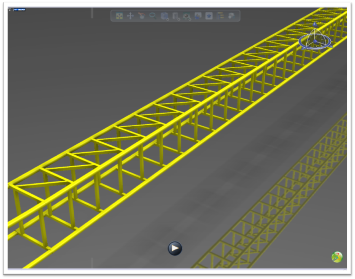
Today, I uploaded a new CAD model to 3D Via in 3D XML format. This is the current state of my next generation version of the cantilevered roller coaster. The main difference has been the change from a cantilevered I beam to a beefier truss configuration.

Thursday, June 24, 2010

CAD Roller Coaster Model Car Concept

Working on a new concept model in part and assembly design. This is the lower chasis. modeled in Catia V5 and screenshot in 3D Via. More to come soon including the 3d xml files.

Friday, February 5, 2010

I Made the 3D Via Top Ten Models of the Week List


The best models uploaded to 3DVIA.com during the week of Saturday, November 1st through Friday, November 7th are highlighted here. Your band now has both a scary guitar, a snare drum and a really cool set of towers to play in, but will the Abstract Propeller and the Flummox Roller Coaster keep the repo men distracted long enough for you to move the Camaro and Sunbeam somewhere safe. You better hope that the Army truck is finished being lined-up on the jig so you've got some back up on the way…otherwise you may end up making friends with the smiley guy in the hearse.

Check it out!

(Mine is the Flummox roller coaster in case you did not know).

Saturday, January 23, 2010

The Future in 3D

If you’ve been following CAD Systems Help you may have seen some of the amusement park ride 3D computer models we have been working on in our spare time (I promise this blog will have more CAD examples than just roller coasters). In those earlier posts, all we presented you with were 2D pictures of the rides. You could only view the model from the view that we gave you. What if you wanted to view the model from a different angle? Well now you can.  We have converted all of our original Catia models to 3D XML format and uploaded them to 3D VIA. Several of our works-in-progress are embedded below for your enjoyment. Feel free to explore the actual 3D models yourself!

For those who are not familiar, 3D XML is a universal, lightweight XML-based format that enables users to share live, accurate 3D data quickly and easily. A free player is provided by Dassault Systemes (you will need to install a plugin in order to view our creations). The models come with no history, meaning you can’t see exactly how they were built, just what the end result is.

One of the coolest features of 3D VIA is the ability to integrate high quality 3D models within Word and PowerPoint documents, which is as easy as dragging and dropping the 3D XML file into the Office document. This also enables users to view interactive, real-time 3D applications in a Web browser or stream them from a website.

What does this mean for the amusement park industry? These tools can be a great resource for ride design and would enable more efficient communication between the manufacturer and the amusement park. Gone are the days of carrying around huge sheets of plain, two-dimensional drawings that take money to print and time to revise. It’s much easier to visualize a new attraction if you can see a model in 3D and even better if the park can zoom in on specific features and view it from any angle. This software enables the park to give instant feedback on what they do or don’t like about their upcoming ride. The biggest advantage of 3D VIA is that it enables all of this to be achieved without the park having to own expensive CAD software.
In fact, another great feature is the complete three-dimensional models can even be viewed on your iPhone! 3D Via’s new mobile app allows you to position and overlay 3DVIA models on your iPhone photos and e-mail or share with friends. Check out an example video:


evisions can be made and viewed in real time, again increasing efficiency and communication. This could help the park and manufacturer save money by decreasing design time. Attractions can be realized quicker and would need less lead time. The parks could save additional money because they wouldn’t need to hire a separate company to build a model of the ride for marketing purposes as they would already have exactly what they needed. It’s a win-win-win situation for operators, designers, and customers.


Intamin Ball Coaster
Vekoma Flying Dutchman
Water slide
Water slide
Wood coaster
Wood coaster
Steel coaster
Steel coaster

Click on the pictures above to go to the live 3D models. This is just a sample of how would work in real world situation (if it isn’t already being done).

Check out our project showcase site.
View some of our other non-amusement park related models.

For more amusement park news and features visit Coaster101.

CATIA Model: S&S Screamin Swing

Today I decided to attempt to model an S&S Screamin Swing thrill ride in CATIA V5 R19. Here are two pictures and the 3D xml of what I made today. It's a little rough around the edges but you get the idea. I made up all of the dimensions since I have no idea what they actually are. I think the scale actually came out quite well. Not as exciting as a roller coaster but the file size is much smaller! You can see some of my other creations at Campus3ds website. Enjoy.


Friday, January 15, 2010

Wicked Twister Roller Coaster CAD Model Tutorial

If you are a frequent visitor to Coaster101, you may have seen some of my CATIA amusement park ride computer models, like this. You may also have been asking yourself or wondering how I created those computer models. Well today I am going to explain in a little bit further detail on the process I have used to recreate those attractions on the computer.

 I use a program called CATIA (Computer Aided Three-dimensional Interactive Application), which is the most powerful and widely used CAD (computer aided design) software of its kind in the world.


 If you’ve ever used No Limits simulator there is an excellent Wicked Twister recreation so I am going to use that to help me out. Keep in mind that this is just one approach of literally thousands of different ways of doing it. If you have a other suggestions I would love to hear them!
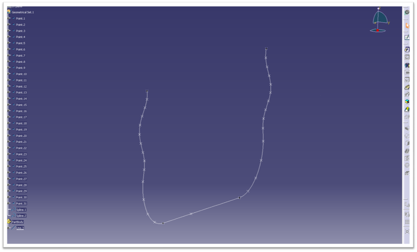
The first thing I did was get the coordinates from all of the node points in the No Limits model. I created all of these points in a CATIA part. Be careful of the axis system, CATIA’s default axis is not necessarily the same as No Limits in terms of which direction is X, Y, or Z is. Next, connect all of the points with the spline command. This is the result thus far. You can see the basic profile layout, also called the center or heartline of the coaster.
wt1
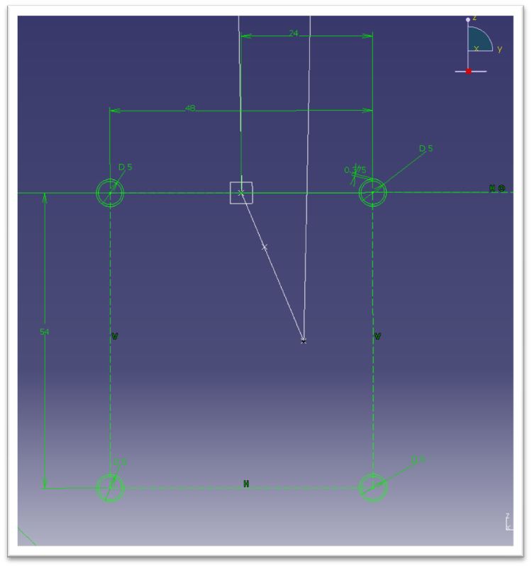
Now we need to make the shape of the track. This are the dimensions I used for the track.

wt2

I have never seen an actual spec from Intamin so I had to do a little investigating and guess work. This is what’ve I’ve come up with. From an old Millennium Force flyer I learned the rails are 5 inches in diameter and only 3/8 inch thick (even at the highest g-force areas). Someone gave me an educated guess that the rails are 48 and 54 inches apart at the centerlines so I went with it. The rectangular tubes that hold the rails together I assumed to be 3 inch square tubing.

The important thing to notice now is that the rails are zero degrees with respect to the horizontal axis. This becomes critical when we get to the two towers and this angle will gradually increase, which makes the twisting helix.
The basis of everything is right here. The centerline and the sketch for the rails.
wt3
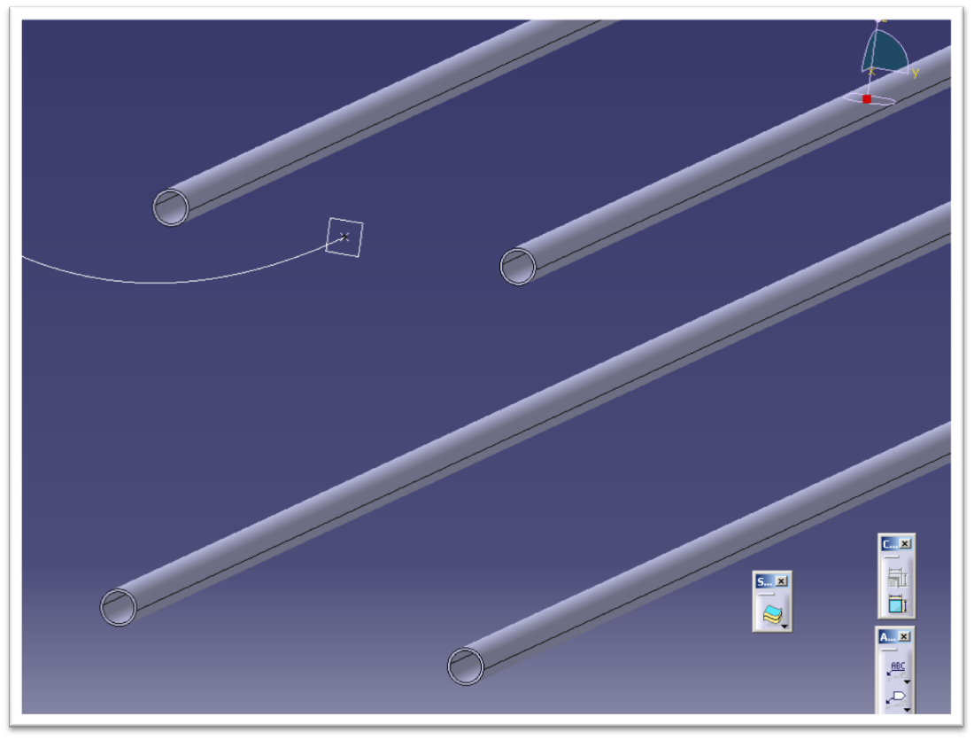
After I created the sketch for the rails, I used the rib command to extrude their shape throughout the length of the station and launch track segments.
wt4
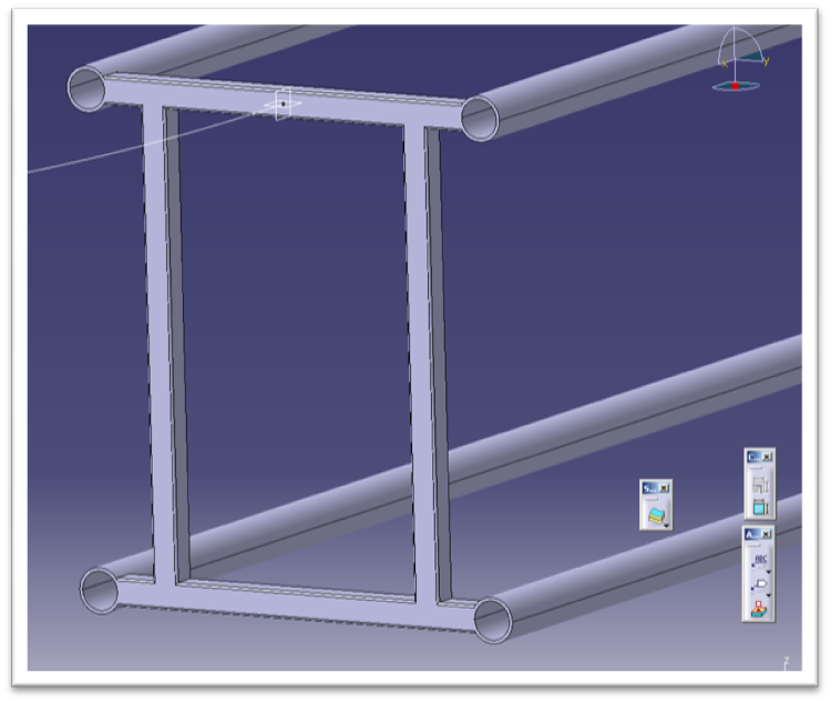
After the rails were created I had to construct the connecting tubes, pictured here.
wt5
I used this image for reference as well.
wt6
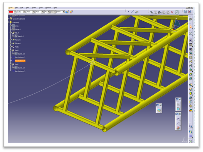
Next I began adding the diagonal cross bars. I only have to sketch one of them on the straightaway then I can simply pattern the rest.
wt7
wt8
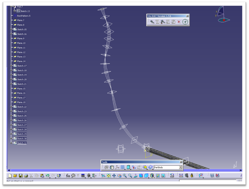
The hard part now is the spikes on the end. Remember the critical angle I mentioned earlier? At every node point starting from the fourth one out of the station the track now rotates 45 degrees about the center. I created points where the rails will go and then connected them with a spline, giving the shape you see here. I can then sketch a circle on the end and rib it through the spline, just like I did earlier, thus creating the rails.
wt9
This is what all of the construction geometry looks like, and by construction geometry I mean all of the points, planes, lines, splines, axis and sketches. These elements are used to construct the solid.
wt10
Next, I ribbed the twisting splines. After all of that, here is the result of our progress, which is as far as I am going to go today. The only other thing I will do now is to quickly construct some simple concrete footers and steel supports for reference.
wt11
I saved my assembly as a 3d xml file and exported it to 3D Via and here it is for your enjoyment.
wt12
wt13
Would you be interesting in learning more and reading additional features like this one? Let us know in the comments!

Thanks for reading.

43BGT8V3B6TP